Calculation Summary
Once the calculation has completed you will be presented with the calculation summary dialogue window which provides detailed information regarding the calculation which you can now review.

|
Source duty |
|
|
The source duty is the minimum flow and pressure required to meet the system requirements or if you have specified a water supply curve in Project Data then this will be the point on the curve. |
|
|
|
|

|
Summary information |
|
|
The calculations summary will provide you with information regarding the calculation which has just been completed. You will find the following information to be most useful:
Design Efficiency: This supposes each head which is operation at its most effective condition (minimum pressure or flow requirement) and disregards and friction loss in the pipework. This is then compared to the actual source flow.
Heads under pressure: The number of heads which are under the required minimum pressure, this should be zero.
Heads under density: The under of heads which are under the required design density as specified in the Project Data - Design Area or individually for each head. Please remember you must also specify the area the head in covering in the pipe data (ADD or EDIT pipe). This is only applicable for projects where design density is required.
Hydraulic gradient: Is calculated as the [Source Flow / (Total Head Area x Design Density)] expressed as a percentage
Overall Flow balance: Is calculated as the [Total flow for the operation heads/The source flow] and expressed as a percentage.
Max node flow error:
Pipes max pd error:
Head max pd error:
|
|
|
|
|

|
Copy to clipboard |
|
|
This button will copy the source pressure and flow to the Windows clipboard as text which you can then paste in to other documents such as Word, Excel or AutoCAD. The text in the clipboard for the above example would be 1448.2 L/min @ 3.021 bar |
|
|
|
|

|
Export to CVS file |
|
|
The Export TO CVS (comma-separated values) file will export the following data to a CVS |
|
|
|
The following data is exported which will be saved in the same folder as the open FHC project
•Area reference (from project data) •Source flow rate in L/min •Source presser in bar •Comments field (from project data)
The CVS file can be opened in Excel and other compatible programs
|


|
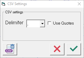
CSV settings |
|
|
The CSV settings will allow you to control the export to the CSV file. |
|
|
|
You can specify the delimiter option "," or "|" or ";" and if you require the output text to be in "quotes". As a default the comma "," delimiter and without quotes is used.
|

|
If you have calculated a sub set of heads (not all heads) then the Part Save button will be available for you to select. The Part Save will prompted you to save the project with a new file name and only the heads which you are selected and calculated will be saved in the new project file.
This is the same the Part Save command on the Calculate - Options, except your are not prompted at the end of the calculation automatically. |
|
|
|
|

|
Optimise |
|
|
Optimise button will open the optimise pipe sizes dialogue box and will allow you to change globally pipe sizes on the system and will instantly update the calculation for your review. Find out more about the Optimise command. |
|
|
|
|

|
Print report |
|
|
Once a calculation has completed you can use the Print Report button to open the Hydraulic Calculation Report. |
|
|
|
|


Related Video
•How to use Head Codes and the HCL files
|
FHC - Reference & Tutorial | Version 2.4 |
Copyright © 2015-2025 Canute LLP | www.canutesoft.com |