TDS 6 : Risers, hydrants and water cannon
The FHC hydraulic calculation software can calculate almost any type of fire protection system where water is discharged from a device this is often a fire sprinkler or water mist nozzle but we can also calculate wet or dry riser outlet, fire hydrants and water cannons. The list is not limited to these devices but they are probably the most common; you can apply the same principles as outlined in this technical data sheet to foam pourers, hose reels and other devices where you know the required pressure and flow at the outlet.
Wet Riser Example
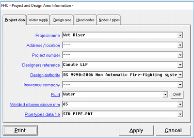
For wet riser system you will start a new project in FHC and draw the pipework as you would with any other system. In the FHC project data it will not be necessary to provide a density of coverage or a design area and these are not applicable for a wet riser system.
|
|
|

For the purpose of this example we going to assume as we have a high-rise building and require two landing valves on the uppermost floors to operate simultaneously with an output of 750 lpm @ 8.00 bar. To model this, we will use the +AF and +AB which are available in the optional items when you use the ADD or EDIT pipe command. You must enter the pressure and flow for the calculation to work so in our example we will enter 750 into +AF and 8.0 into the +AB text boxes, FHC will use this information to automatically calculate the required K-factor (metric value) for the output device and will also ensure that the minimum pressure is achieved.
Once the calculation has been completed you can check your requirements against the calculation by looking at the head summary report [Reports -> Head Summary].

The following image bellow is showing the EDIT pipe dialogue box and highlighted in the red is where you will enter the pressure and flow requirement in the +AF and +AB text boxes.

The FHC project which is shown below is of a wet riser system which is use the techniques which are described above and is available for you to download.

+A Command
Adjacent to the two commands we have been using (+AF & +AB) is a third command +A this is an optional command and you can specify an area in m2. If you enter an area into this box FHC will calculate the design density given the flow rate which has been discharged from the device at the node number.
Add Length command
We have also used another technique which is helpful to clarify the FHC drawing, the horizontal pipe between node 170 and 180 has been drawn as 1m in length however the actual length of this pipe is only 0.3m so we have subtracted 0.7m by using the added length with a negative number (1.0 – 0.7 = 0.3m). You will often find that you can simplify the drawing by using the horizontal pipe length and added length together this is especially true for risers and hydrant systems but you can only use this command for horizontal pipes as FHC must know the correct length of vertical pipe so it can calculate the static pressure.

Hydrant option
FHC also has a hydrant option but this may be described as a hose stream allowance the difference between the hydrant option and the +AB and +AP is that with the hydrant option we only specify a flow rate. This flow rate is then added to the flow rate in the system but is not pressure dependent you use this command to specify an additional flow allowance or hose stream allowance and is often used in the fire sprinkler system designed to NFPA 13 or FM global standards.
Related Topics
Download a PDF copy of TDS6 Risers - hydrants - water cannon.pdf
TDS#: 6, Issue: 1, Date: April
|
FHC - Reference & Tutorial | Version 2.4 |
Copyright © 2015-2025 Canute LLP | www.canutesoft.com |